
Nickel Alloy Fasteners Torque Chart
Advanced Tension Management
The engineering, specification, and application of high-nickel alloy fasteners represent one of the most critical and highly specialized domains within modern industrial mechanical design.
As global industries continue to push extreme boundaries of operational pressures and thermal limits, the reliance on advanced metallurgical compositions has increased exponentially. Fasteners manufactured from exotic materials such as Inconel, Monel, Hastelloy, Waspaloy, and A-286 offer unparalleled resistance to severe corrosive media and catastrophic oxidation. However, their successful deployment necessitates an exacting, scientifically rigorous approach to torque and tension management.
The application of excessive tightening torque can lead to plastic deformation of the bolt shank, irrecoverable thread stripping, or instantaneous catastrophic fracture. Conversely, insufficient torque invites joint separation and leakage. This comprehensive reference evaluates the intricate relationships between applied torque, resultant tension, boundary lubrication, and material properties across a broad spectrum of industrial nickel alloys.
Mathematical Mechanics of Torque & Preload
The fundamental objective of tightening a threaded fastener is to elastically deform the bolt shank, acting effectively as an ultra-stiff spring. The universally accepted engineering equation governing the relationship between the applied tightening torque and the resulting bolt tension is:
- T = Total tightening torque measured in foot-pounds (ft-lbf).
- K = Torque coefficient (Nut Factor), a dimensionless empirical value representing frictional dynamics.
- D = Nominal outer diameter of the bolt in inches.
- P = Target bolt clamp load or preload measured in pounds of force (lbf).
To derive the target clamp load (P), engineers calculate the Tensile Stress Area (A) and establish the proof load (typically 90% of yield strength). The target clamping load is conventionally established at 75% of the calculated proof load to introduce a critical safety margin.
Clamp Load (P) = [Yield Strength × A × 0.90] × 0.75
Tribology, Lubrication, & Galling Prevention
For high-nickel alloys, dry friction coefficients are notably high. Unlubricated or "dry" nickel alloy fasteners typically exhibit a K-Factor ranging from 0.20 to 0.22. When relying on dry installation, the variation in actual clamping force can fluctuate by 30-40% ("bolt scatter").
Thread Galling (Cold Welding): When the threads of a bolt and nut are engaged under heavy pressure, sliding friction physically strips away the protective oxide film. The raw metal surfaces fuse together under intense compressive loads. To prevent this destructive failure mode:
- Apply high-quality anti-seize lubricants (Molybdenum disulfide drops K-Factor to ~0.13).
- Maintain a distinct hardness differential of at least 50 Brinell between the bolt and mating nut.
- Avoid high-speed pneumatic impact wrenches; tension slowly and continuously.
- Utilize Cold-rolled threads over cut threads for optimal intermediate smoothness.
Waspaloy (UNS N07001) Torque Chart
| Bolt Dia (in) | TPI | Stress Area (in²) | Clamp Load (lbf) | Dry Torque (ft-lbf) | Lubricated Torque (ft-lbf) |
|---|---|---|---|---|---|
| 1/4 | 20 | 0.0318 | 3,434.4 | 15.7 | 9.3 |
| 5/16 | 18 | 0.0524 | 5,785.0 | 33.1 | 19.6 |
| 3/8 | 16 | 0.0775 | 8,556.0 | 58.8 | 34.8 |
| 1/2 | 13 | 0.1419 | 15,665.8 | 143.6 | 84.9 |
| 5/8 | 11 | 0.2260 | 24,950.4 | 285.9 | 168.9 |
| 3/4 | 10 | 0.3340 | 36,873.6 | 507.0 | 299.6 |
| 1 | 8 | 0.6060 | 66,902.4 | 1,226.5 | 724.8 |
| 1 1/4 | 7 | 0.9690 | 106,977.6 | 2,451.6 | 1,448.7 |
| 1 1/2 | 6 | 1.4050 | 155,112.0 | 4,265.6 | 2,520.6 |
Inconel 625 (UNS N06625) Torque Chart
| Bolt Dia (in) | TPI | Stress Area (in²) | Clamp Load (lbf) | Dry Torque (ft-lbf) | Lubricated Torque (ft-lbf) |
|---|---|---|---|---|---|
| 1/4 | 20 | 0.0318 | 1,287.9 | 5.9 | 3.5 |
| 5/16 | 18 | 0.0524 | 2,169.4 | 12.4 | 7.3 |
| 3/8 | 16 | 0.0775 | 3,208.5 | 22.1 | 13.0 |
| 1/2 | 13 | 0.1419 | 5,874.7 | 53.9 | 31.8 |
| 5/8 | 11 | 0.2260 | 9,356.4 | 107.2 | 63.4 |
| 3/4 | 10 | 0.3340 | 13,827.6 | 190.1 | 112.3 |
| 1 | 8 | 0.6060 | 25,088.4 | 460.0 | 271.8 |
| 1 1/4 | 7 | 0.9690 | 40,116.6 | 919.3 | 543.2 |
| 1 1/2 | 6 | 1.4050 | 58,167.0 | 1,599.6 | 945.2 |
Inconel 718 (UNS N07718) High-Temperature Dynamics
Unlike solid-solution alloys, Inconel 718 is hardened through the precipitation of complex secondary phases, achieving an ambient minimum yield strength of 150.0 KSI (150,000 PSI). Its torque parameters are calculated using the universal tension formula but adjusted upward to reflect this extreme yield threshold.
Inconel 718 is rated for continuous extreme service from cryogenic depths (-423°F) up to 1,300°F. Engineers must carefully factor in its dynamic thermal conductivity, which increases from 77 BTU·in/ft²·h·°F at 70°F to 148 BTU·in/ft²·h·°F at 1,200°F, significantly altering the thermal expansion rate during rapid heat cycling.
Hastelloy C276 (UNS N10276) Torque Chart
| Nominal Dia (in) | TPI (UNC / UNF) | Torque Dry (ft-lb) [UNC/UNF] | Torque Lubricated (ft-lb) [UNC/UNF] |
|---|---|---|---|
| 1/4 | 20 / 28 | 4.5 / 5.2 | 3.4 / 3.8 |
| 5/16 | 18 / 24 | 9.3 / 10.3 | 7.0 / 7.7 |
| 3/8 | 16 / 24 | 16.5 / 18.6 | 12.4 / 14.0 |
| 1/2 | 13 / 20 | 40.2 / 45.3 | 30.1 / 33.9 |
| 5/8 | 11 / 18 | 79.9 / 90.5 | 60.0 / 67.9 |
| 3/4 | 10 / 16 | 142.0 / 158.0 | 107.0 / 119.0 |
| 1 | 8 / 14 | 343.0 / 385.0 | 257.0 / 289.0 |
| 1 1/2 | 6 / 12 | 1039.0 / 1169.0 | 779.0 / 876.0 |
Monel 400 (UNS N04400) Torque Chart
| Bolt Dia (in) | TPI | Stress Area (in²) | Dry Torque (ft-lbf) | Lubricated Torque (ft-lbf) |
|---|---|---|---|---|
| 1/4 | 20 | 0.0318 | 4.5 | 2.9 |
| 3/8 | 16 | 0.0775 | 16.7 | 10.9 |
| 1/2 | 13 | 0.1419 | 40.8 | 26.5 |
| 5/8 | 11 | 0.2260 | 81.2 | 52.8 |
| 3/4 | 10 | 0.3340 | 144.0 | 93.6 |
| 1 | 8 | 0.6060 | 348.5 | 226.5 |
| 1 1/4 | 7 | 0.9690 | 696.5 | 452.7 |
| 1 1/2 | 6 | 1.4050 | 1,211.8 | 787.7 |
A-286 (UNS S66286) Torque Chart
| Bolt Dia (in) | TPI | Stress Area (in²) | Clamp Load (lbf) | Dry Torque (ft-lbf) | Lubricated Torque (ft-lbf) |
|---|---|---|---|---|---|
| 1/2 | 20 | 0.1599 | 11,584.8 | 96.5 | 62.8 |
| 5/8 | 11 | 0.2260 | 16,373.7 | 170.6 | 110.9 |
| 3/4 | 10 | 0.3340 | 24,198.3 | 302.5 | 196.6 |
| 1 | 8 | 0.6060 | 43,904.7 | 731.7 | 475.6 |
| 1 1/2 | 6 | 1.4050 | 101,792.3 | 2,544.8 | 1,654.1 |
Metric Standard Fastener Torques (N·m)
Maximum recommended tightening torques (lubricated, 85% proof load) for cross-referencing strength equivalents.
| Metric Thread Size | Grade 8.8 (N·m) | Grade 9.8 (N·m) | Grade 10.9 (N·m) | Grade 12.9 (N·m) |
|---|---|---|---|---|
| M8 | 28.8 | 32.3 | 41.3 | 48.3 |
| M10 | 57.3 | 64.1 | 81.8 | 95.7 |
| M12 | 99.8 | 112.0 | 143.0 | 167.0 |
| M16 | 248.0 | 277.0 | 354.0 | 413.0 |
| M20 | 500.0 | N/A | 690.0 | 809.0 |
| M24 | 865.0 | 1,195.0 | 1,395.0 | N/A |
| M30 | 1,719.0 | 2,377.0 | 2,774.0 | N/A |
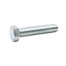
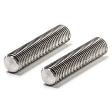
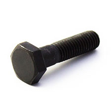
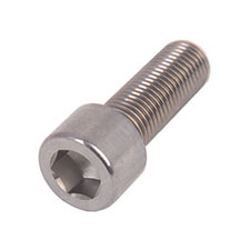
High-Performance Alloy Hardware
Request QA/QC Engineering Support
Require custom torque profiling, NABL testing, or specific boundary lubrication analysis for your EPC project?
Submit Your Technical Inquiry
Your reliable manufacturing partner for high-quality industrial fasteners and global export.
Quick Links
Contact
- Address: Plot No - 14, Dewan And Shah Udyog Nagar, Golani Naka, Vasai East, Vasai-Virar, Waliv, Maharashtra 401208
- Email:
sales@anankafasteners.com
yogita@anankafasteners.com
globalsales@anankafasteners.com